Watermanagement
System for Combustion Engine Test Stands
Introduction
Due to the high utilization of the existing coolant
facility, the Austrian Magna subsidiary company 'Engineering Center Steyr GmbH
& Co KG' decided on a new water management system. In test benches for
combustion engines, cooling water is essential for, e.g., operating the heat
exchanger of the main cooling system and the eddy current brake. Closed or
semi-closed cooling cycles reduce water consumption and increase economic
efficiency. Concerning semi-closed systems, additives and particles evaporate
less than water; the impurity of water and hence the electrical conductivity
increase. Some water has to be replaced by conditioned water ('desalination') at
certain levels of conductivity. Cooling systems, like micro controller equipped
units for softening or conductivity control, are widely spread. However, these
stand-alone solutions will not act together sufficiently. Therefore, an
innovative overall control setup was designed, which meets the given demands.
System Description
FieldPoint 2000 RT was selected to ensure high reliability and expandability
of the controlling unit as well as short code development time. Each bank
consists of one dual channel terminal base with 4xPT100, 4x4-20mA, 2x0-10V input
channels and one 16x digital output module. The control unit allows saving data
locally, providing an easy data upload to a local server. A user interface is
running at the local server to give information about the current and historical
status or to request up/down load of data. Figure 1 shows the block diagram of
the setup.
The developed control unit performs several tasks (monitoring
of water level, temperature, pump pressure, conductivity, further the supply of
softened water, water hardness control, regeneration of the softening unit). No
further nod is required. The same master unit controls both of the independent
cooling cycles. In case of emergency, each water treatment unit can supply both
cooling systems. All relevant measurement data are logged automatically what
enables the deduction of important trends, like the connection between water
consumption and temperature.

Figure 1 Block Diagram of the Water Management System
Each cooling unit is equipped with sensors for:
· Conductivity
· Water consumption
· Water level (ultrasonic)
· Temperature
· Pressure
Additional sensors (hardness, pH-value) can be embedded easily.
To guarantee high quality refill water, each facility uses a
twin tank alternating softening system. If one tank is run-down after draining
the specified water volume, it is switched to a regeneration status while the
other tank continues the supply. Since the required amount of refill water
varies with cooling power, temperature, etc., the capacity of the softening unit
usually must consider even peak requirements. By using a new innovative
controlling system the unit can be scaled down just to cover the average need.
Unlike many of the conventional controlling units, the developed system enables
subsequent regeneration only if the brine is ready. If no sufficient time span
for regeneration of the brine is provided, hard water will enter the system
causing fatal consequences like calcification of the pipes and of hot surfaces
of breaks and heat exchangers. Settings for either one or two brine barrels
provide the fastest regeneration without any risk of overrunning the system.
Through calculating the overall water hardness and operating a bypass valve
accordingly, the required hardness of feed-water can be achieved.
Software Features
A watchdog function is periodically checking the regeneration process and
valves. If a measurement channel provides out-of-range data a warning or error
condition arises. In such case, a snapshot of all parameters is stored and an
alarm (flashlight/horn) is activated. However, the internal error is cleared
after each software cycle. The optical/acoustical signal is latched until it is
acknowledged. To prevent loss of information due to a power failure, important
data like regeneration phase or valve positions are periodically being stored at
a temporary file on the flash RAM of the controller. After the device has been
rebooted, the temporary file supplies all information to the controller, which
continues operation at the point of interruption.
The on-line user interface (Figure 2) enables monitoring of
data, which are provided by the controller via DataSocket™. They return the
actual status of all channels, error messages, regeneration information, and
valve status. The off-line mode displays charts and trends of historical data
stored in the database. A request-for-data uploads the latest data from the
FieldPoint 2000 flash RAM to the database. Through LabVIEW HTTP-Server and CGI,
both interfaces can be operated by a Web browser at any workstation
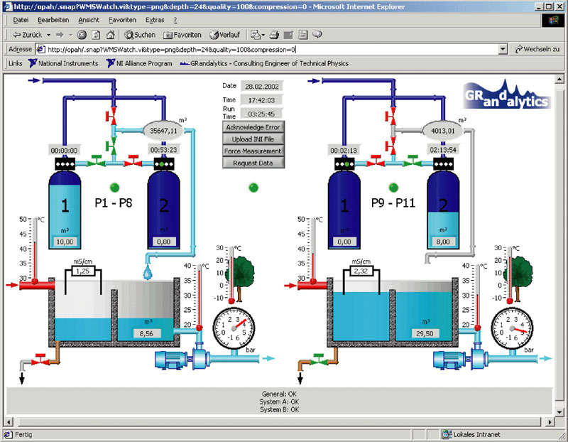
Figure 2 Screen Capture of the User Interface
Several calibration parameters and limits are stored in an
initialization file. Changes of settings are made at the local server.
Thereafter, the user requests a download of the new file to the controller. The
controller sends a request-for-file with local and remote file name to the
server, which transfers the file via FTP followed by an OK tag. The controller
checks the file for validation and replaces the old initialization file. This
allows a safe update without interrupting the controller. The upload of
measurement data is done similarly. For convenience, a new file is created each
month; data compression and automatic size check prevent an out-of-memory of the
controller.
Conclusion
This new network-based water management system is successfully in use and
provides an innovative overall solution replacing the previous non-interacting
controllers. The reliability of the FieldPoint RT controller together with
software safety features prevents system crashes that can cause a considerable
loss of production time. Fully automated measurements make the operation much
more convenient, as well as time- and cost-effective by lowering personnel costs
and down time. The new system supports higher water capacity at a good quality,
reducing shut downs and above-mentioned fatal consequences caused by high water
hardness. It enhances flexibility as each water treatment unit can supply both
cooling systems by cross switching. As just one economic result, preventing
complete draining of the cooling basins saves water. Furthermore, the modular
setup of the system allows future extension in a low-cost manner and adaptation
with regard to other facilities. Considering all these factors, up to 10% of
total costs can be saved.
This application was published in national and international
independent journals and awarded at the NIDay 2003 in Vienna, Austria and at the
NIWeek 2003 in Austin, TX:
AUTlook
12/02-01/03
Page 26-28
Control
Solutions International 03/04 Volume
77 Page 57-59
Best Application
Award
NIWeek 2003