Automatisches
Kabeltestsystem
Einleitung
Die Firma ‘Elektrotechnik Wild GmbH’ in A-4400
St. Ulrich produziert eine große Anzahl von Kabeln für verschiedenste
Industriezweige.
Die routinemäßige Qualitätskontrolle der verschiedenartigen Kabeltypen muss
daher durch Automatisierung zuverlässig und kosten
It is therefore of
great importance to continuously check the quality of a variety of cable types
in a reliable, timesaving, and cost-effective manner.
In the LabVIEW™ development environment, it is possible to design a software
application that realizes this reliable quality control tool regarding different
product specifications. In combination with the PCI-DAQ cards, the requirements
of the automated testing system could be matched also from the hardware point of
view.
The testing system consists, on the one hand, of several hardware components
like the NI-DAQ cards as well as a printed circuit board with a comprehensive
and reliable setup. On the other hand, a software with a number of features like
for self test, continuity test and electric strength has been developed. Both,
hardware and software, are described in the following in more detail.
Hardware
The
Hardware part consists of a master printed circuit board with eighty high
voltage relays for switching the chosen wires, the continuity checking system,
the high voltage test equipment, as well as some discharging components. A
picture of the master printed circuit board is shown in figure 1. Figure 2 shows
a detail of the layout.
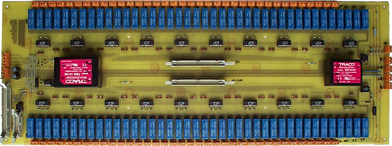
Abbildung
1:
Hauptsteuerkarte
mit Relais und Stromquellen für Durchgangstests
The
controlling of the relays is being provided by driver ICs. Their
coil current is checked by a shunt, an amplifier and DC/DC converter.
According to the producer, lifetime of the relays is limited by approximately
5x10⁸ cycles. However, in order to extend the lifecycles of the
contacts, switching will be done in a condition that is currentless as far as
possible. For this purpose, a photo-MOS relay switches the on-board low voltage
source for continuity test. The high voltage power supply is remote controlled.
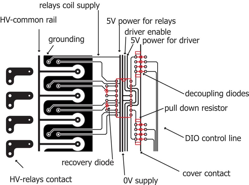
Abbildung
2:
Ausschnitt aus dem Leitplattendesign
For
the protection of the PCI-DAQ card, a feed back of the continuity check is
carried out by a highly insulating opto-coupler. The response from the high
voltage unit is received by the remote control terminal. Decoupling diodes
ensure instant shutting of the relays in case the protective cover is opened,
not depending on the DI/O card.
The
high voltage is applied by a high tension power pack (type HCE 7-1250POS) by the
company F.u.G. Elektronik GmbH, D-83024 Rosenheim. The device supplies voltages
up to 1250 V.
Software
Features:
The Cable Testing Software ‘CaTe
1.0’ is a user friendly, list-controlled program that guarantees a quick
handling by an easy-to-use and self-explanatory user interface.
An initialization file contains all data (like calibration data, relay
assignments, initialization of the DAQ cards, etc.), which are necessary for a
proper functioning. In order to adapt the testing system in case the hardware
has been modified, this file can be adjusted by the user. It is loaded at the
beginning of the program.
Another file, the parameter file, is also loaded at the start of the program.
This spreadsheet includes data that are specific for the cable being tested. It
can be easily modified with regard to adding new types of cables to the test
program. All data that are relevant for testing, like the number and assignment
of wires, the test voltage, measurement time, charging and discharging time,
events for report generation and so on are covered by this file. The result of
the testing as well as possible system errors are stored in two log files.
Reports can be generated either automatically or by user call, for series as
well as for single tests.
For safety reasons, the program is periodically checking up if the protective
cover of the system is closed.
Funktion
Nach dem Programmstart prüft ein Selbsttest die ordnungsgemäße Funktion jedes
einzelnen Relais und der Steuerkarte. Danach schließt der Entladekreis und speist
5V Testspannung ein um die Durchgängigkeit zu bestätigen. Das
Hochspannungsnetzteil wird bei 2 unterschiedlichen Spannungen getestet, zuerst
bei geöffnetem Kreis zum Isolationstests und abschließend kurzgeschlossen zur Überprüfung
der Strombegrenzung.
Das Ergebnis des Selbsttests
The
status of the self test is shown in an information window at the control panel.
Any occurring errors and their causes will be stored in the system log file.
Furthermore, a pop up window shows a corresponding error message and the user is
encouraged to close the application. Figure 3 shows the user interface.
After the self test has passed, a drop down list for cable selection appears.
The menu shows different cable types loaded from the parameter file. By a mouse
click, the type can be selected with a corresponding picture and description.
Thereafter, the number of the required cables has to be chosen and the test can
be started with the start button. A progress bar shows the status of the
continuity test and the high voltage test.
After finishing this part, a respective message is shown and a button appears
for generating the desired report (if not already generated automatically). In
case of a series test, which means more than one cable of the same type, a
complete report can be generated. This complete report contains cable
description (type, number of wires and insulation, testing voltage, comments…)
and test results (OK or type and location of failure).
The number of the remaining cables is counted down in a display.
If a cable fails the test, the affected wires will be shown at the status window
and stored in the cable log file. Different background colors of the status
window emphasize the test result (cable passed or failed). In order to test the
next cable of a series the user just has to open the cover, replace the cable
and the test is started again by closing the cover; no button has to be pressed.
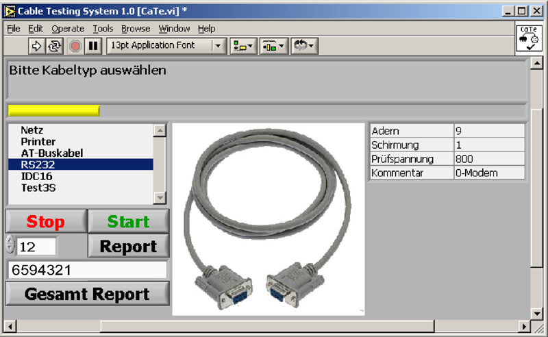
Abbildung
3: Bildschirmaufnahme der ‘CaTe 1.0’ Benutzermaske
Nach
ende eines Tests werden Barcodeetiketten für aller erfolgreich überproften
Kabel ausgedruckt und der Programmablauf beginnt erneut mit der Abfrage
der nächsten Kabeldaten.
Schlussfolgerung
Die Firma ‘Elektrotechnik Wild GmbH’ in A-4400 St. Ulrich produziert
eine große Anzahl von Kabeln für verschiedenste Industriezweige. Bis jetzt
erfolgte die Überprüfung der Kabel manuell mit erheblichem Zeit- und
Personalaufwand. Daher entschloss sich die Firma für die Automatisierung dieses
Produktionsschrittes. Die Softwareanwendung ermöglicht eine verlässliche
Qualitätskontrolle bezüglich unterschiedlichster Produktspezifikationen.
Zusammen mit den PCI Cards werden alle Anforderungen auch von Seiten der
Hardware abgedeckt. Dadurch kann die Prüfung der Kabel in einer zeit- und
kostensparenden Weise durchgeführt werden.