| Engineering for Measurement and Automation |
 |
| Technischer Stand / Last update: 2020-05 |
|
|
|
High Dynamic Fuel Cell Test Station Why dynamic testing? As fuel cells moved into focus as an environmentally friendly power source for automotive applications, the standards for fuel cell test stations have changed. Formerly used for long-term, steady-state testing, now fast transient analysis and drive cycle simulations are mandatory. Hence, a new system was designed from scratch with prospects of high dynamics, Hardware-in-the-Loop simulation, platform independent communication, and expandability. Uncompromising safe operation is crucial for the unit under test and the operator alike. Unattended 24/7 testing, high temperatures and currents, H2 and O2 use require an unreserved reliable system. What is unique? Based on National Instruments CompactRIO, an inherently safe, self-sustained control system was developed. FPGA and Real-Time employment facilitate multiple layers of safety and extremely fast alarm counteracting while harboring the entire control strategy. Although no dedicated PC is required to run the test station, data can be exchanged with multiple nodes via UDP. Computers of different platforms may transmit and receive data in parallel, forming a unique network of simulation, scripted testing, data storing and visualization while achieving performance that is unrivaled among fuel cell test stations. The modular software architecture and new signal conditioning hardware allow quick adaptation and are also suitable for economic retro-fitting of existing test stands. What is the gain? Fuel cell test stands for dynamic applications have so far been upgraded standard test stands. Hence, they are not optimized, run by a Windows-based host PC, and simulations need a CAN interface to hook-up. All this results in response times of 800ms and more for load following. With the new breed of test stations, the response time could cut down to less than 50ms. No additional hardware is required to hook-up simulation targets. Since safety systems are encapsulated and centralized on the RT controller, customer get open-source code of the functional RT kernel and the main GUI to implement their specific capabilities without compromising the overall safety and reliability. How it works
At a glance: the controller - Pure Real-Time (RT) controller,
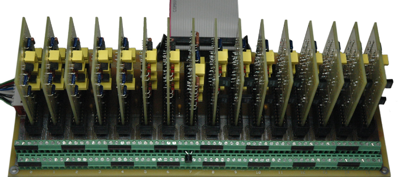
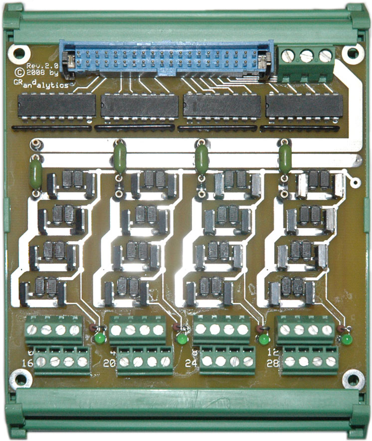
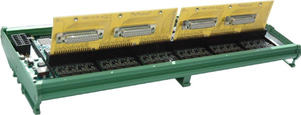
no PC required to run the test station At a glance: connectivity and signal conditioning - 2 x 32 differential, analog input channels
with modular signal conditioning (left)
At a glance: the GUI - Optional, open-source GUI with intuitive
P&ID and DIN-standard like controls
Graphic User Interface (GUI) with interactive
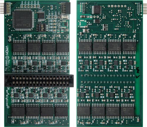
Piping and Instrumentation Diagram (P&ID) High-
End cell
voltage monitor and diagnosis system for fuel cell stacks - 16 channel per module, stackable up to 240 channels total
Please contact us for more information |